Category Archives: Uncategorized

190 SL brakes and Carburettor tune

A nice 1959 190SL which the owner said was pulling badly to the right has come in for some work, but needed a full set of wheel cylinders to make safe.

The Brakes weren’t releasing properly and the home made push rod was too long .a heavier version imitating an original ajustable push rod was fabricated. The device in the right picture is the fuel tank sender which had rusted up, along with a half a tank of very old fuel

A bit difficult to see but there are spots on the exhaust manifold…it’s petrol dripping from the carbs. Not Good…..

An example of what i found in the brakes . This was the right rear hub, the small round thing is a push point on the brake shoes, there is supposed to be a forked rod pushing on this when the hand brake is applied. It was behind the shoe,so no hand brake. the larger round part is one of four self adjustors on the rear brakes. i had to strip those and rebuild them as the thrust washers were broken. Everything is working as it should now. Carb over haul is next.

W114 Coupe Rust Repair.

This is a 1973 W114 Coupe, a 280E which has had some horrific rust repairs in the past. The Owner has asked me to replace the rust damaged floors which will require me to cut out the old ones to be replaced with new ones.

the pic on the left shows the type of repair, tape covered in black tar ,which has to be removed.

Center pic shows another mess covered in black stuff while the right hand pic from another car demonstrates what it is supposed to look like.

Rear Floor Next to hand brake mechanism , which shows a paper clip being used to hold the link pin in place.

Another part of the floor showing a rust hole full of expanding foam .

Another Veiw under anther W114 showing what the Drivers side floor and handbrake cable pocket should look like .Note the rust free jack point. on the Blue car this has rusted badly.

Left side jack point and what they are supposed to look like. right is NOT what we want.

This is what the left side rocker panel end and floor will look like when repairs are finished.

How the sills and floor should meet .this has largely disappeared on the blue car.

together in the shop.

The Sad remains of the floor … Skilfully hidden by covering with bits of rubber, lots of Polyfilla and tar.

A sample of the debris removed from one floor section.

450SLC repairing rusted out sections and severe panel damage from previous repair.

The battery has been leaking onto the passenger side (Left) inner fender and rusted out the floor. In this picture the rusty part of the footwell,next to the firewall has been removed.

This is the peice from a donor wreck used to replace the rusted part. As can be seen all of this has to be inserted to replaced the parts damaged by leaking battery acid.

This is the part that was removed, as can be seen it involved a lot of work with much panel damage covered up by previous repairers .

With the rusted part removed including the sill and jack point the damage doesn’t look so bad.

The replacement section in Place

The Circle illustrates a gap,this was where a peice madein the same shape as the Sill Section but 1.5 mm smaller has been placed inside ,then used to weld the two parts together and add strength.

So the next part is to replace the right rear quarter . this had been “repaired” in the past but wasn’t the correct shape and was full of body filler . The spot welds have been drilled out ,’unpicked’ . The center peice below the rear screen has to be removed to fix rust,but that comes later.

In this shot, the arrow points to a wrinkle in the B pillar where it’s been bent in the past in an accident . The outer skin has now been removed making this repair easier.

This is the right hand wheel house

The wheel house has damamge which has to be straightened before the new skin can be fitted .

In this picture,it shows how the old skin was startng to rust on the inside because the window trim was leaking. Below, the area is indicated by the orange arrow .the yellow arrow indicates where holes were punched into the panel In the past, in an attempt to pull a dent out . this did more damage ,requiring the replacement of this part.

The wheel house has lots of dents made when the previous attempt at repair was made.

1974 Mercedes C107 rebuild.

A customer has engaged us to rebuild his 1974 450SLC. This car has been rebuilt and maintained throughout it’s life including some time off the road in Storage. the paint is tired and flaking off so it will stripped back to bare metal,rust repaired and repainted before reassembly. it’s also rather special in that it will be four speed manual.

The car has been stripped to the bare shell in preparation for Stripping to bare steel .

The shell is very dusty after being in another shop for two weeks.

This is the right hand corner of the body, the body has little rust compared with others i have done over the years. that is a hole in the centre.
Top right corner of the cowl reveals more holes,but this is the result of bad repair work in the past It is how water got into the cowl made the rust hole at the bottom.
Another close uip of the right hand corner.
Manual Flywheel for the 450SLC, plus clutch. it is a used item but in very good condition.
it came from this engine, a M116 3.5 Djet engine which has had some work in the past and despite appearances, actually runs…and is for sale.
Both Cylinder heads are stamped with a rebuilders mark and have over heat tell tale plugs fitted.
Clutch and four speed trans as removed from the Donor car.
Damper on the 450 Engine covered in residue from a leaking water pump.
Suspected leaking head gaskets ,probably over heated because of the faulty water pump.
More external oil leaks
Engine is up side down in the engine stand ,oil leaking from rear of head.
Oil seepage from left hand head.

Mercedes Benz 300 SEL 6.3 repairs part 2

IMG_0438

This is the Sump for the 6.3 M100 Engine .On the right front corner. Oil was leaking through the weld and the side of the pan was full of cracks. All were leaking.

IMG_0437

The welds were very porous and leaking badly.

IMG_0545

The easiest way to fix all of the cracks and bad welding was to cut the bottom off and make a whole new bottom and weld it in place.


IMG_0552

The Engine was rolled over to get the Sump off and to replace the crank seals . The crank shaft had to come out ,but bearing damage was revealed.

IMG_0553

Number 7 Conrod bearing was flogged out and the conrod bore distorted . The Big end bore was resized.

IMG_0554IMG_0551

Careful measuring of the crank revealed it to be free of any damage  so will be cleaned and reinstalled.

IMG_0588

The Bores are ok and only needed a light hone to restore the crosshatch pattern. The rings are worn and will be replaced.

to be continued….

Mercedes 220SE Restoration. August 2019 update!!

IMG_0459

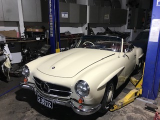
The final coats of paint are on and just need polishing now.

IMG_0460

IMG_0562

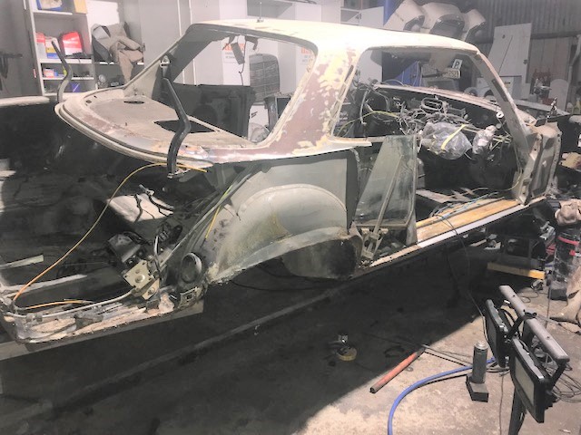
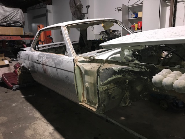
Moved out of the paint booth and taken off the Rotisserie .The shell is now on the hoist to receive all the under pinnings

IMG_0563

The 6.3 is now headed into the booth to be finished .Here,it’s on the chassis rack which is on wheels

IMG_0564

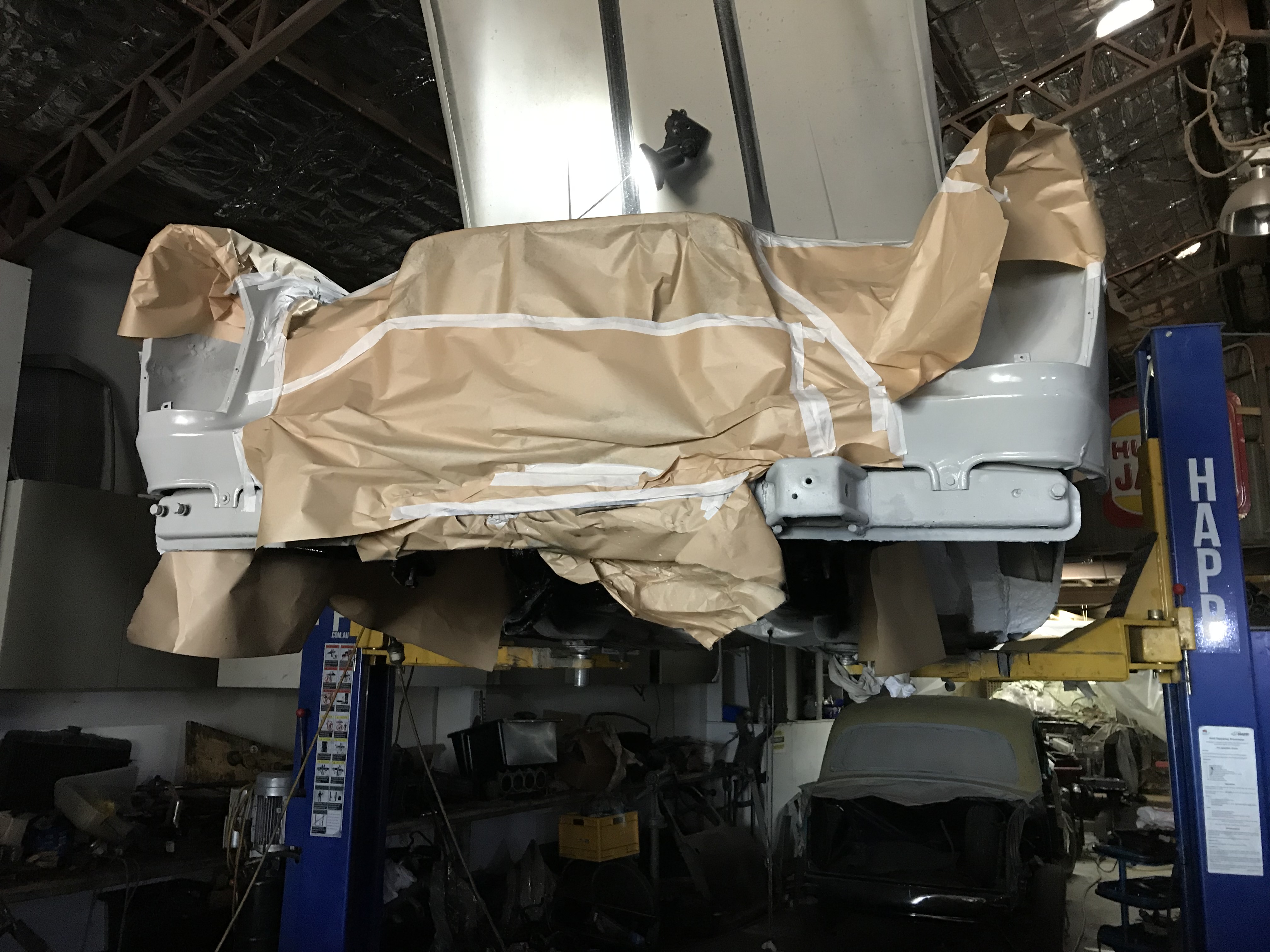
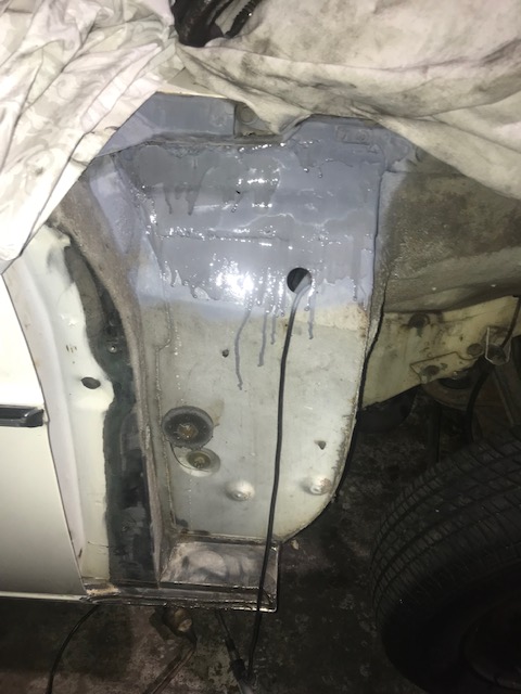
The Engine bay needed a bit of touch up so here it’s masked up so the paint overspray can’t escape

IMG_0572

The finish is Satin Black but here it’s still wet so it looks glossy. This type of paint takes a few days to set properly.

IMG_0574

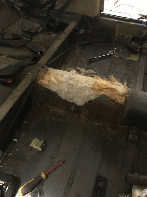
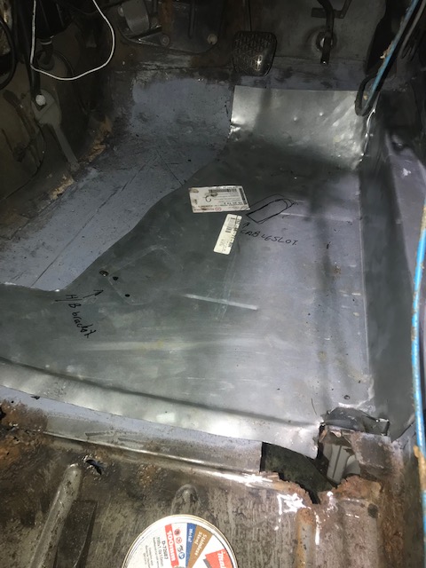
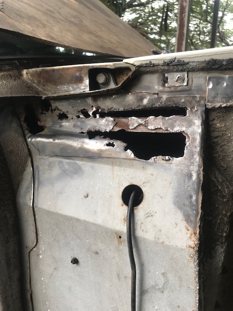
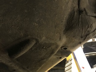
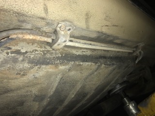
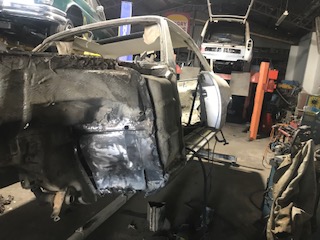
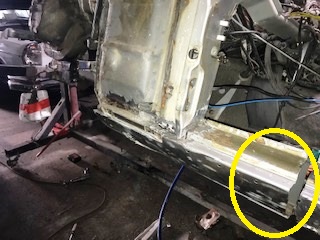
Here is the trans tunnel and I’ve been refitting the fuel and brake lines. All of the clips have new rubbers and the plating restored.

IMG_0582

The steering column is in place ,along with the front part of the wiring loom ,Horns and brake lines. The pad on the firewall has been replaced with a new one .All Australian Built Mercedes Car had a black Engine bay.

IMG_0583

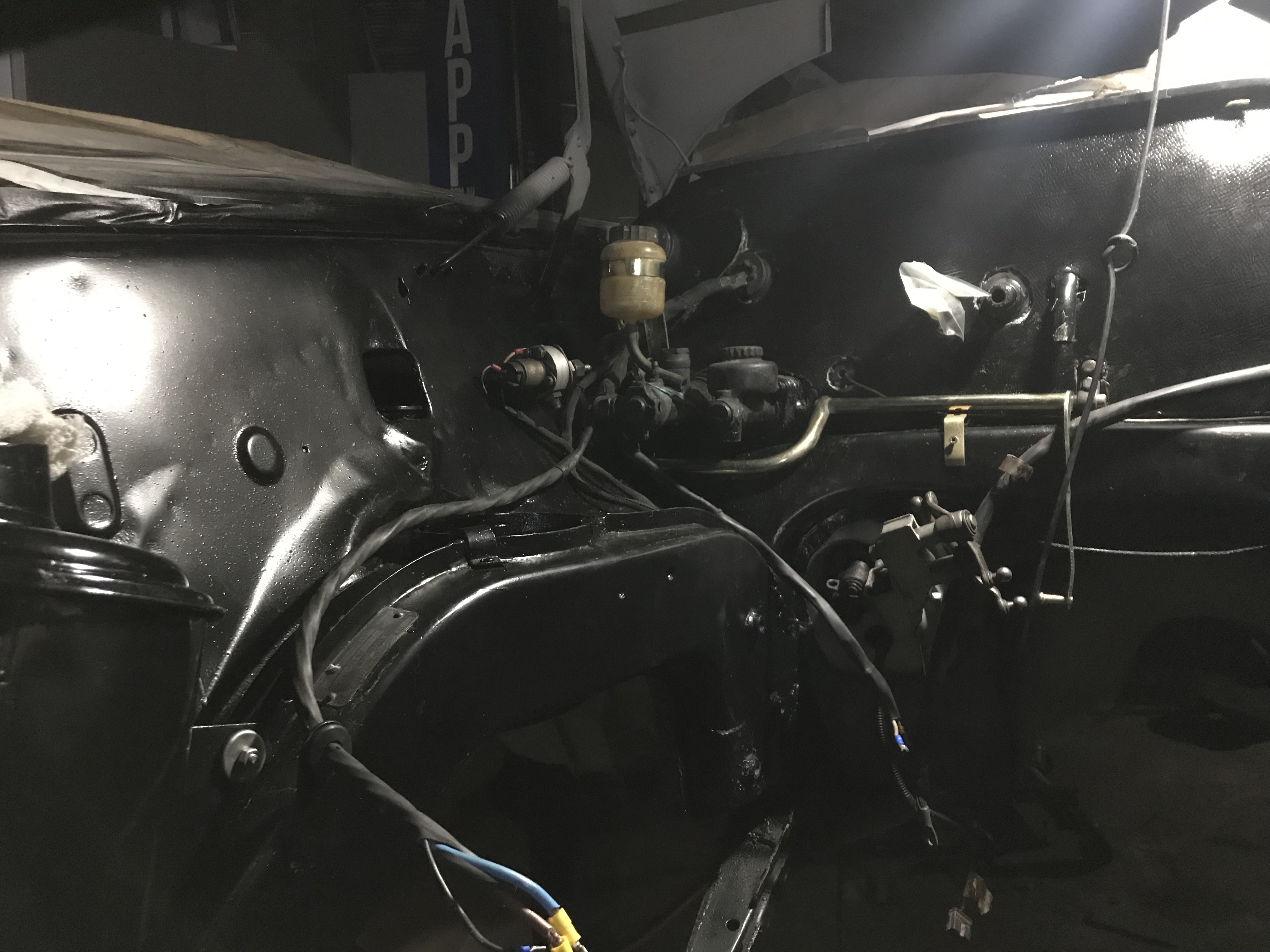
The cable here is the new generator cable ,with the Cold start Valve ,which is different to all of the later model 220SE’s which have the cold start valve in the intake manifold .

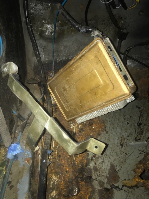
In the lower left of the picture is the aircleaner which has been restored . The brake reservoir has had the bracket restored

IMG_0584

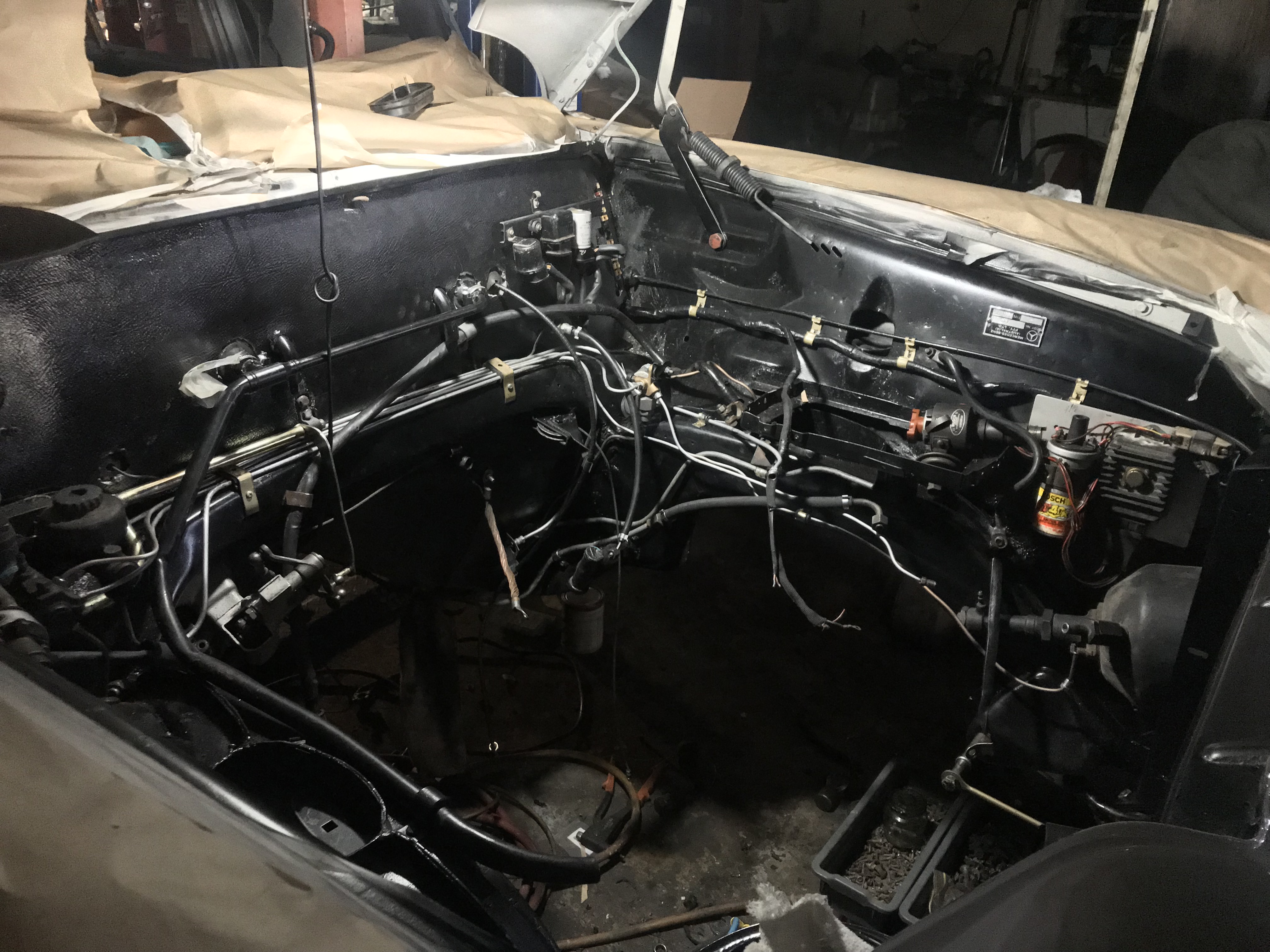
The cables,the cold start and flasher relays,ignition coil new brake lines are in place. The injection pump cold start wiring are in place .The Heater feed pipe is in place ,after being remade in copper to prevent it rusting out again . The little plaque on the left inner fender is the Body tag from the Australian Mercedes Assembly plant in Melbourne with it’s Australian only body number.

IMG_0595

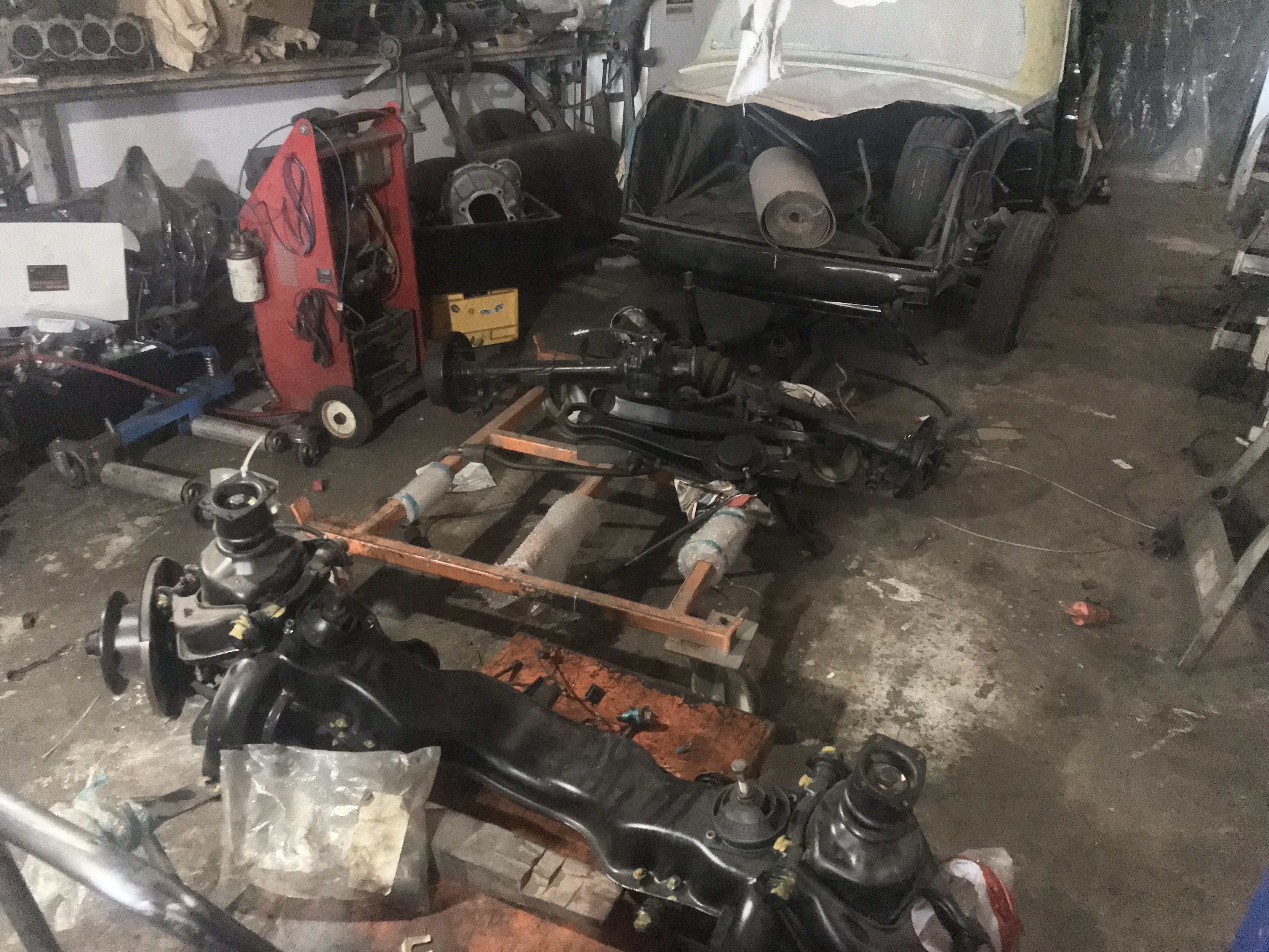
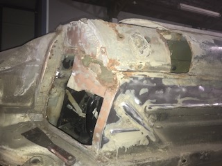
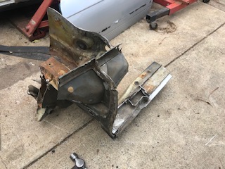
The Front and rear ends are nearing readiness for installation .

IMG_0596

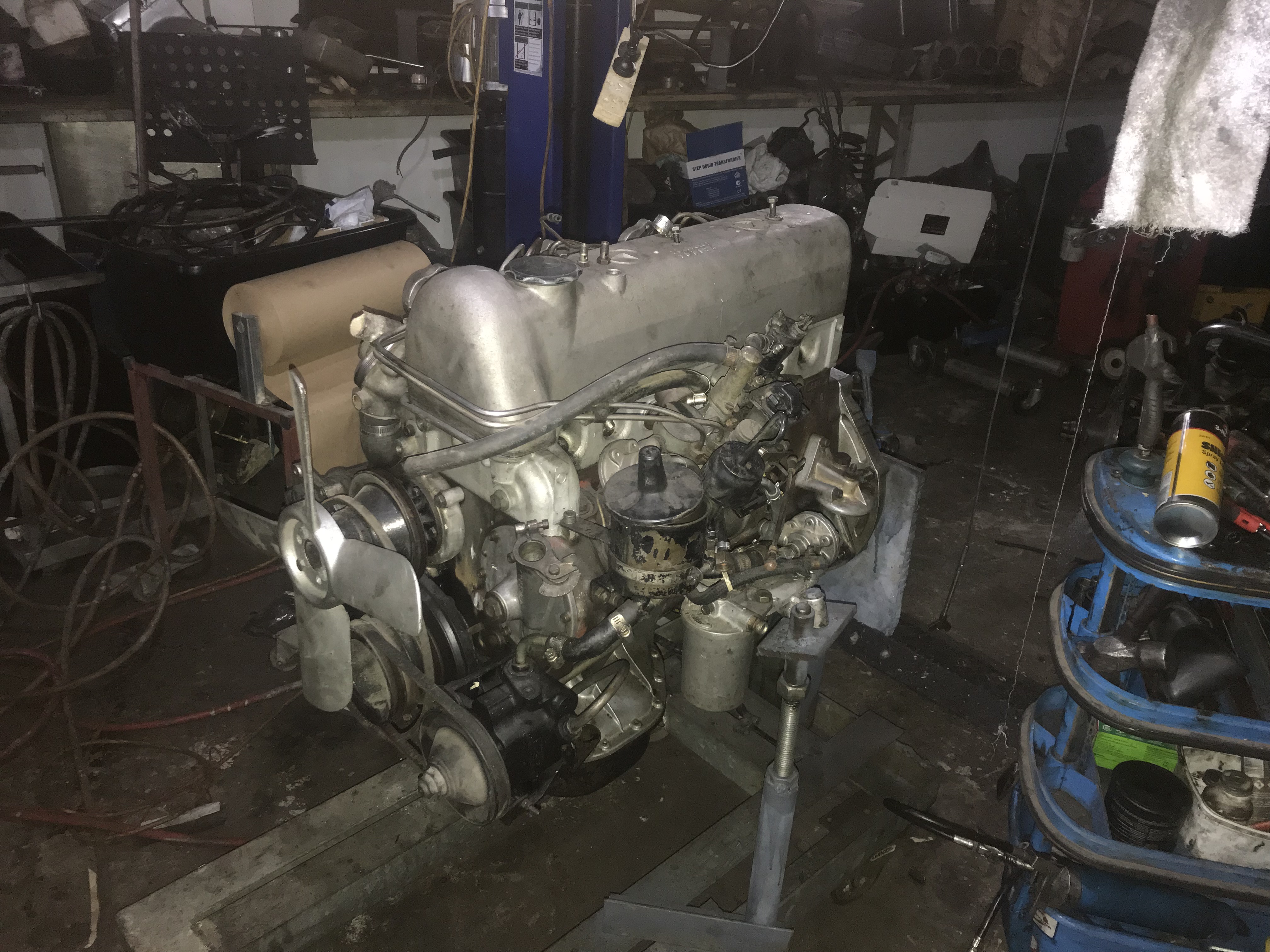
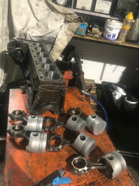
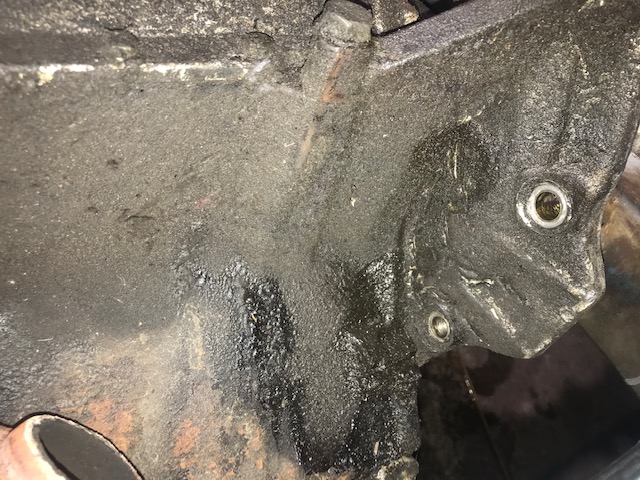
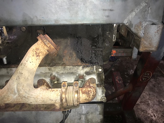
Here is the engine as removed from the Car initially .It needs a lot of oil leaks rectified and the valve stem seals replaced. I did a leak down test and it has good sealing and compression’s on all six cylinders.

IMG_0604

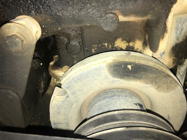
a couple of days later and the crank seals have been replaced, The Damper had to be replaced because someone in the past had fitted it in the wrong place(the damaged one is sitting on the frame under the engine. .I have no idea of how they managed to set the ignition timing . The large black bracket is for the air conditioning compressor. All of the hoses have been replaced . There is a new water pump air bleed pipe ,and all of the mounting bolt holes needed to be repaired with helicoils.

All of the exhaust valve oil seals had been fitted incorrectly ,so they leaked badly.

Both intake and exhaust seals were replaced on all cylinders.

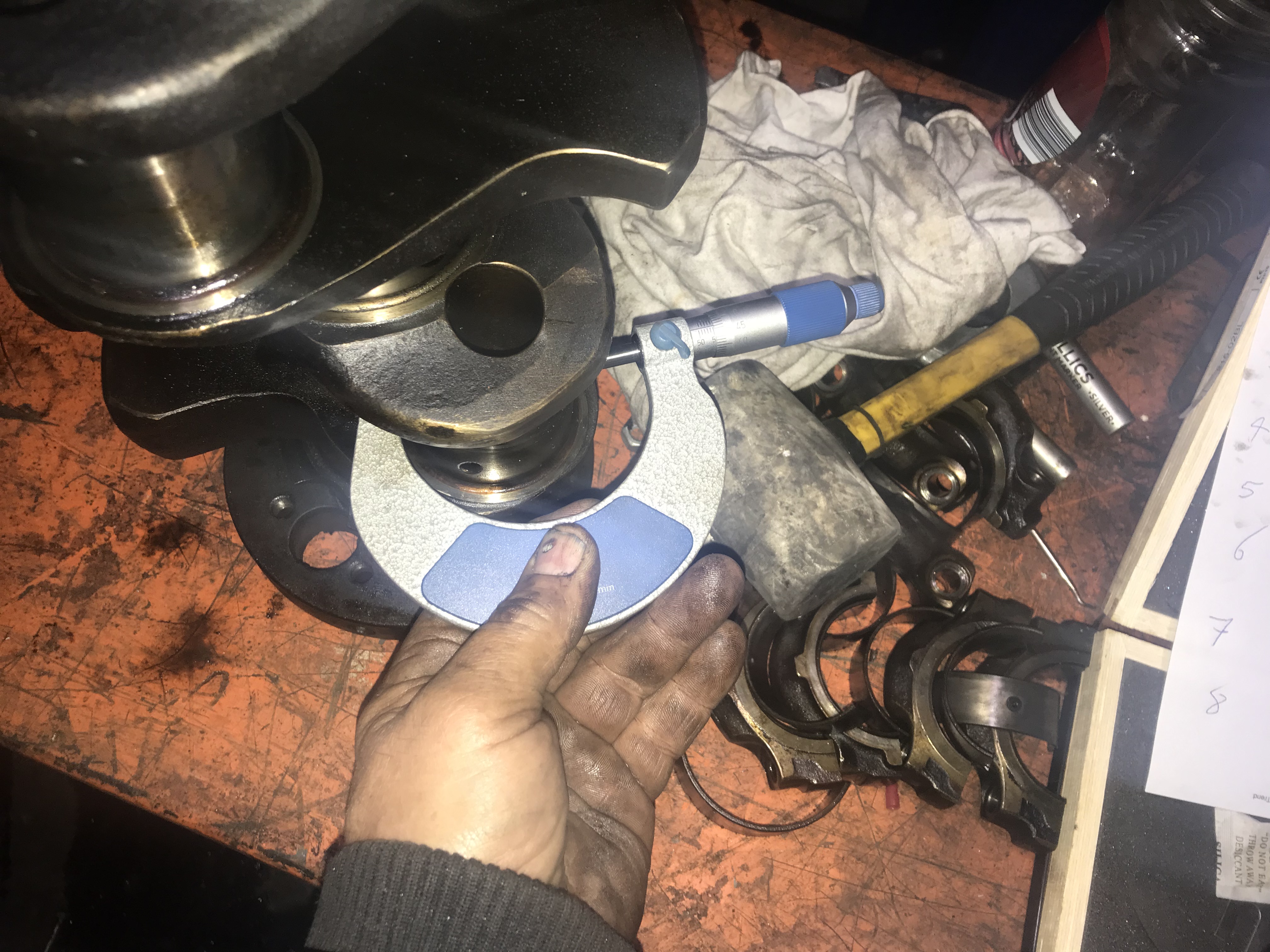
The timing chain is worn out as is the tensioner so those will have to be replacedto get the engine performing properly.

IMG_0610

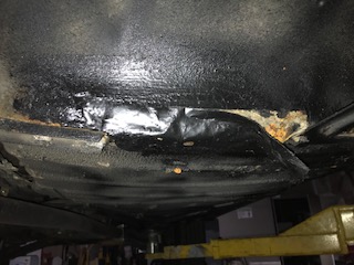
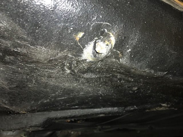
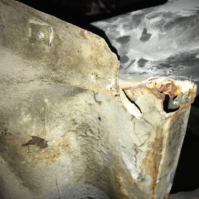
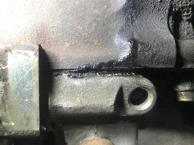
This is the inside of the Thermostat housing and as can be seen ,the seat for the bottom part of the thermostat itself has been eaten away over time so it wouldn’t have been working properly. This is very important with the mechanical fuel injection system which relies on the coolant circulating to the injection pump to set the cold and warm running mixtures.

IMG_0612

Here, the corroded one on the left is compared with a good part.

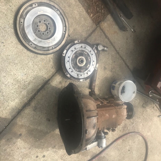
Next… reassembling the engine trans together and fitting to the front in preparation for fitting into the car.

Mercedes 300SEL 6.3engine stand

I needed a very heavy duty engine stand to support the Engine from the 6.3 project.

I had a heavy engine stand but it wouldn’t hold an M100 Engine ,so the plan was to use the end of a W112 rear axle with it’s heavy bearing and flange .

IMG_0280

Normally I’d say this was rare part (very few W112 cars were made)

A length of the axle housing was cut off in the lathe.

IMG_0284

The actual axle shaft was then measured to length (250mm) a section of the axle taper was machined flat,so the shaft was parrallel ,then parted off in the lathe.

IMG_0282

parted off axle stub Seen here sitting on a base originally from a ute crane (crane on the back of a pickup truck ) These were welded together so I have a face plate to mount the engine.

IMG_0283

The axle housing stub was then welded to the engine stand to provide a rotating point.

IMG_0285

I then made a Fork,which supports the weight of the engine at the mount arms ,the bell housing end bolts to the two brackets to support the rear of the engine.

IMG_0288

Here is the engine ,upside down ,in preparation to repair the cracked sump and leaking rear main seal.

IMG_0287

Eventualy i will add a reduction gear to the shaft at the rear so the engines can be rotated. They roll easily enough on the stand but there is nowhere to lock it in place yet.


Mercedes 220SE restoration ,paint work continues

IMG_0242The lour coat has gone on ,4 coats followed by 3 coats of clear.  This will now be flatted back after a weeks curing. The car will then be flow coated ,then polished.

IMG_0245

This the first lot of clear coat which has to be flatted ,Sanded smooth then recoated to bring up the gloss and add depth to the Finish .

IMG_0244

Mercedes Benz 300 SEL 6.3 repairs

This is part of a 6.3 rebuild which began as a simple gear box swap,but while working underneath the car i noticed a lot of damage and some really badly repaired accident damage .Apart from rust in the usual places the front cross member was rusted out and the car was 50mm shorter on the left side.This pic shows the state of the left hand side bumper support cross members . Not only bent it was rusted through . To repair it in the past,someone had simply welded a patch over the top of the worst dent and welded the bumper bracket to that.

KONICA MINOLTA DIGITAL CAMERA


KONICA MINOLTA DIGITAL CAMERA

Here is the Left hand upper part of the fender to radiator support panel. It wasn’t welded together as it should have been. 


KONICA MINOLTA DIGITAL CAMERA

The entire front section had to be replaced. The rust in the bottom of the center section can be seen here . The panel was distorted completely out of shape .


KONICA MINOLTA DIGITAL CAMERA

The engine has to be removed to gain access to further damage hidden under the firewall and to check the chassis integrity. 


KONICA MINOLTA DIGITAL CAMERA

The circle indicates the bend in the left hand chassis rail . The front end of the rail was bent down 25mm .Above it there are creases which had to be worked out. 


This is the upper part of the inner fender panel ,which was bent back.

IMG_0026

The inner side of the rail was heated carefully and force applied to bend the leg back up again.

IMG_0025

The outer part came straight with a lot of work.


I used a laser to make sure the both sides were even .

KONICA MINOLTA DIGITAL CAMERA

With the front parts removed ,the damage to the chassis extension can be seen clearly .The left hand extension piece(arrow)  was actually bent to the left .Both pieces needed to bent straight. 

KONICA MINOLTA DIGITAL CAMERA

The Right hand side was OK,not requiring any work. 

IMG_0149

The next step was to repair the damaged inner fender and weld up parts where it was torn from the radiator support panel .

IMG_0198

As the panels are straightened out it was important to constantly check the chassis was still within specs.

IMG_0257

This the left hand outer part of the footwell . It has been pulled back into shape as it was pushed back contributing to the shorter measurement on the left side.

IMG_0027

The new parts are shown here temporarily clamped into place to ensure the car is coming back to shape.

IMG_0072

Almost there!.

IMG_0148

After a few hours work straightening.

IMG_0192

I use a trammel to measure from a set position under the chassis where there is a hole which takes one end,this is the other where a set measurement shows the crossmember here is correctly placed.

IMG_0190_LI

The yellow arrow points to the trammel rod and the red arrow shows the needle end in the chassis measurement aperture.

IMG_0173_LI

The Yellow arrow here points to the laser line where i am making sure the crossmember is fitting level .

IMG_0170

As soon as i am 100% sure the crossmember is sitting in the correct place etc,I weld the rear part to the chassis extensions.

IMG_0169

IMG_0155

IMG_0199

The radiator Support panel is now lined up and checked with the laser before clamping and welded into place.


The trans tunnel was very badly damaged in the past,probably from a frontal impact,and was 50mm shorter than it should have been.

KONICA MINOLTA DIGITAL CAMERA

in this picture the tell tale ripples in the trans tunnel . The engine had been pushed back in an accident in the past ,leaving the impression of two bell housing bolt heads in the firewall . 

KONICA MINOLTA DIGITAL CAMERA

The hole in the tunnel on the right of this picture is the access for the starter motor bolts. There is little room in a 6.3 engine bay. 

Inside the car ,various parts were damaged ,such as the heater case and this,the dash board brace where the bolts have been sheared off.

IMG_0461_LI

IMG_0484_LI

The firewall wasn’t only pushed back,but the welds for the tunnel have been torn away.

IMG_0172

The inner fender to firewall end has rusted and where the parts were repalced in the distant past,they weren’t welded but simply brazed together.


I removed the tunnel So I could straighten it out and pull the firewall back out again .

IMG_0140


In the past someone had used heat to try and removed dents in the tunnel,where the black burn marks are.


The other interesting this was the method used to hold the gear shift in place.

IMG_0099 (1)


The lever was stuck in place with Sika flex.

IMG_0103


IMG_0092


The sika flex was stripped off  and the tunnel put back into shape the shifter base was also bent so that was repaired .

IMG_0152

IMG_0157

The side flanges where the car is spot welded to the car were replaced as was the front end where it is fuse welded to the firewall aperture .IMG_0158

IMG_0163

Under the car,the cross member on the tunnel was bent,so that has been straightened also .

IMG_0165

In the spray booth.

IMG_0166IMG_0171

This the firewall on the passenger side (Right hand Drive) .The side panel was replaced in the past and Brazed into place. Rust has taken hold so this whole piece has to be removed and replaced.


There is rust in the Sill /Rocker section at the front to be repaired.

KONICA MINOLTA DIGITAL CAMERA

Front end of the right hand sill/rocker section.

IMG_0517

The hole in the upper edge of this picture is from rust forming behind the jack point on the right hand side.

IMG_0518

The mess revealed under the coats of bituminous underseal.

IMG_0512

I cut the outer skin off and as can be seen it’s was pretty rough inside.

IMG_0514

Cleaned up in preparation for new steel to welded into it.

IMG_0542

With the new peice welded in place, a spare guard is bolted in place to check fit .

Next: welding the tunnel into place and repairing the remainder of the rust .